M8 / M12 Field-Wireable Connector Assembly Guide
Step-by-step guide to assembling Fadeya M8/M12 field-wireable connectors — parts overview, cable preparation, wiring order, screw-terminal torque and a final QC checklist.
Field-wireable (solder-free) connectors let you terminate a sensor or actuator cable on site — no crimping tool, no soldering iron, no pre-made cordset inventory. A correctly assembled M8 or M12 screw-clamp connector holds IP67, survives vibration, and can be re-terminated in minutes.
This guide walks through the full assembly of a Fadeya M8 / M12 field-wireable connector, from cable preparation to final verification. Allow about five minutes per connector.
1. What you need
| Item | Note |
|---|---|
| Wire stripper | For jacket and conductor insulation |
| Small flat-blade screwdriver | Sized to the terminal screw |
| Open-end spanner | For the cable gland and coupling nut |
| Cable | Match the connector's approved cable OD range (see datasheet) |
⚠️ De-energise before you start. Never assemble or re-terminate a connector on a live circuit.
2. Parts overview
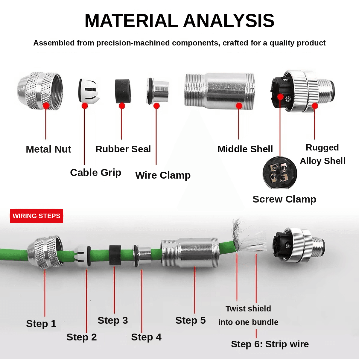
| # | Part | Function |
|---|---|---|
| 1 | Metal nut (cable gland nut) | Compresses the grip and grommet; provides strain relief and the cable-entry seal |
| 2 | Cable grip (strain-relief claw) | Grips the cable jacket so pull force never reaches the terminals |
| 3 | Rubber seal (grommet) | Seals around the cable jacket to deliver IP67 |
| 4 | Wire clamp (contact carrier / insert) | Holds the conductors and carries the screw terminals |
| 5 | Middle shell (barrel) | Houses the insert and carries the coupling thread |
| 6 | Screw clamp terminals | Make the conductor connection — no soldering, no crimping |
| 7 | Rugged alloy shell | Die-cast body; mechanical protection and EMC shielding |
3. Cable preparation
3.1 Strip the outer jacket to the length specified for your series (typically around 20 mm). Do not nick the braided shield or the conductor insulation.
3.2 Twist the shield into a single bundle. On shielded (EMC) versions, fold the braid back over the jacket so it makes contact with the metal shell when assembled. A loose, splayed shield is the most common cause of intermittent EMC problems.
3.3 Strip each conductor to the specified length (typically 4–6 mm). Twist the strands tightly — no whiskers. A single stray strand across two terminals is enough to cause a short.
📏 Verify before publishing: strip lengths, conductor cross-section (mm²/AWG) and cable OD range differ between M8 and M12 and across Fadeya series. Confirm the exact values against the datasheet for the part you are assembling, and keep them consistent with the figures printed on the product page.
4. Assembly
Thread the components onto the cable in this order — the sequence matters, because each part is trapped by the one that follows it.
Step 1 — Metal nut
Slide the cable gland nut onto the cable first, threads facing the connector end. It is fitted last but must go on first.
Step 2 — Cable grip
Slide the strain-relief claw onto the cable, tapered end facing the connector.
Step 3 — Rubber seal
Slide the grommet on, narrow end first. Make sure the grommet size matches your cable OD — an undersized seal will not reach IP67, and an oversized one will not grip.
Step 4 — Wire clamp (contact carrier)
Slide the insert onto the cable and push it back along the cable to keep it out of the way while you terminate.
Step 5 — Middle shell
Slide the barrel onto the cable and push it back as well. Both it and the insert will be pulled forward at the end.
Step 6 — Terminate the conductors
Insert each conductor into its terminal and tighten the screw. Observe the standard pin assignment and wire colours:
| Pin | A-coding signal | Wire colour (IEC 60947-5-2) |
|---|---|---|
| 1 | +24 V DC | Brown |
| 2 | Signal / NC | White |
| 3 | 0 V DC | Blue |
| 4 | Signal / NO | Black |
| 5 | Functional earth / PE | Grey |
Tighten each screw firmly but do not over-torque — stripped terminal threads cannot be recovered. Typical screw-clamp torque is around 0.2 N·m; confirm the value on your datasheet.
Give each conductor a light pull test before moving on. A conductor that slips out now will fail in the field.
5. Final assembly
- Seat the insert — pull the contact carrier forward into the barrel until it clicks or bottoms out.
- Slide the barrel forward over the insert and thread it home.
- Slide the grommet into the rear of the barrel so it sits squarely in its seat.
- Slide the cable grip forward so the claw closes around the jacket — not around the individual conductors.
- Tighten the metal nut onto the barrel. Hand-tight plus a quarter turn with a spanner is normally sufficient. Pliers are not a substitute and will round the hex.
- Check the strain relief — pull the cable firmly. Movement should be taken by the jacket, with no load on the terminals.
6. Verification checklist
Before the connector goes into service:
- Every screw terminal tightened and pull-tested conductor by conductor
- No stray strands visible outside any terminal
- Shield braid twisted, folded back, and in contact with the metal shell (shielded versions)
- Grommet seated square and matched to the cable OD
- Cable grip clamping the jacket, not the conductors
- Cable gland nut tightened
- Continuity and pin-to-pin short check on a multimeter
- Insulation resistance check if the application specifies one
- Coupling nut on the mating connector hand-tightened
7. Mistakes that cause field failures
| Mistake | Consequence |
|---|---|
| Wrong threading order | Connector cannot be closed — full rework |
| Grommet not matched to cable OD | IP67 lost, moisture ingress |
| Grip clamping conductors instead of jacket | Conductors work-harden and break |
| Stray strand between terminals | Intermittent short, very hard to diagnose |
| Over-tightened terminal screw | Stripped thread, terminal must be replaced |
| Shield left loose | EMC noise on analogue and encoder signals |
| Coupling nut left hand-loose | Vibration loosens it, connection drops |
Need the right connector for your cable?
Field-wireable connectors are specified by series (M8 / M12), coding (A / B / D), pin count, cable OD range and shielding requirement. Send us your cable specification and environment — vibration, washdown, temperature — and we will confirm the matching part numbers and the correct grommet size.
Request a quote → · Browse M8 series → · Browse M12 series →
Fadeya Co., Ltd. — Make Your Automation Project Easier