RJ45 Field-Wireable Connector Assembly Guide
Step-by-step guide to terminating a shielded industrial Ethernet / PROFINET cable with a tool-less RJ45 field-wireable connector — no crimp tool needed.
Terminate a shielded industrial Ethernet cable on site — no crimp tool, no soldering, no patch-cord inventory. This guide covers the shielded RJ45 field-wireable connectors: the 4-contact RJ45-M04S-SH (straight) and RJ45-M04A-SH (right-angle) for 10/100 Mbit/s, and the 8-contact RJ45-M08S-SH and RJ45-M08A-SH for Gigabit Ethernet. All four terminate the same way; the photos show a 4-contact model. Allow about two minutes per connector once you have done one.
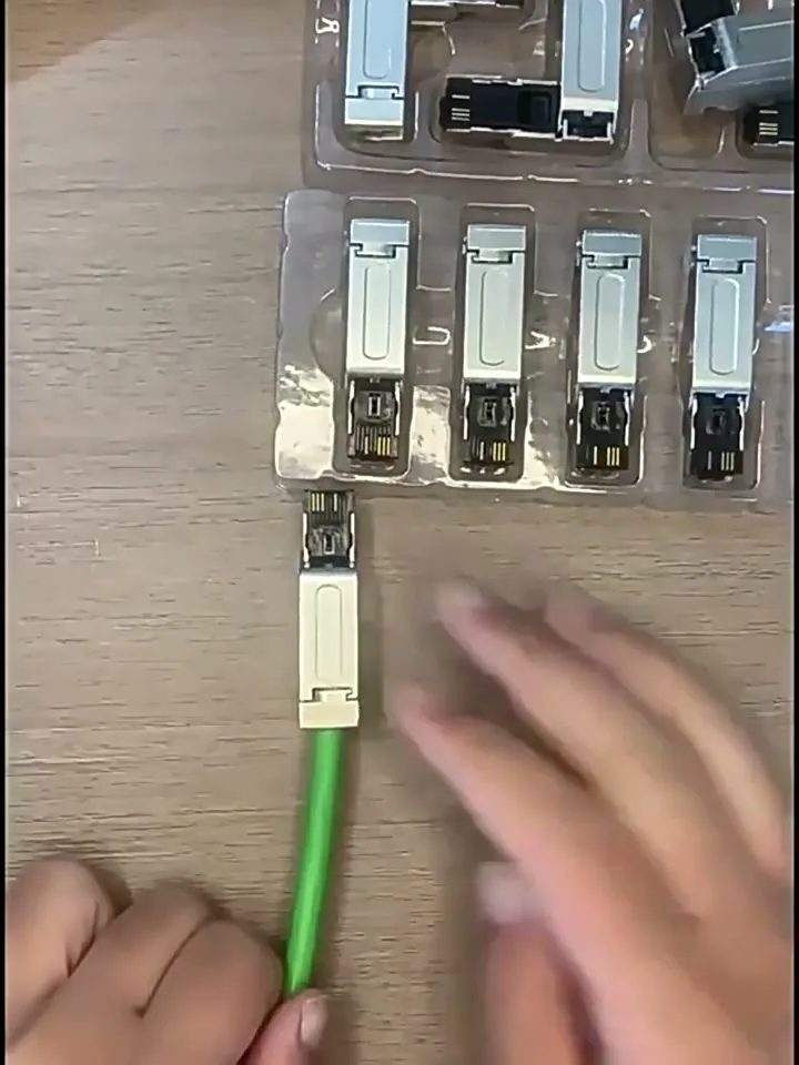 The finished shielded RJ45 field-wireable connector on a green industrial Ethernet cable.
⚠ De-energise before you start. Never assemble or re-terminate a connector on a live network segment. If the port supplies PoE, lock it out first.
1. Know your connector
| Model | Shape | Contacts | Typical use |
|---|---|---|---|
| RJ45-M04S-SH | Straight | 4 (contacts 1–2 / 3–6) | Standard drops, panels with room |
| RJ45-M04A-SH | Right-angle | 4 (contacts 1–2 / 3–6) | Tight spaces, side-exit runs |
| RJ45-M08S-SH | Straight | 8 | Full 4-pair wiring, Gigabit Ethernet |
| RJ45-M08A-SH | Right-angle | 8 | Full 4-pair wiring, Gigabit Ethernet, side exit |
Specifications: data rate 10/100 Mbit/s (M04 models), 1 Gbit/s (M08 models) · shell copper-zinc alloy, nickel-plated · buckle locking · IP20 · 95% humidity (no condensation).
The 4-contact M04 models carry the two pairs used by 10/100BASE-TX. For Gigabit Ethernet, which needs all four pairs, use the 8-contact M08 versions. For PoE applications, please contact us to confirm suitability.
2. What you need
| Item | Note |
|---|---|
| Wire stripper | Matched to the cable jacket |
| Flush cutters | To trim conductors evenly |
| Cable | Shielded industrial Ethernet cable, OD inside the connector clamp range — 2-pair (e.g. PROFINET Type B/C, Cat5e) for M04 models, 4-pair (Cat5e or better) for M08 models |
| Cable tester | Optional, but strongly recommended for the first few terminations |
3. Parts overview
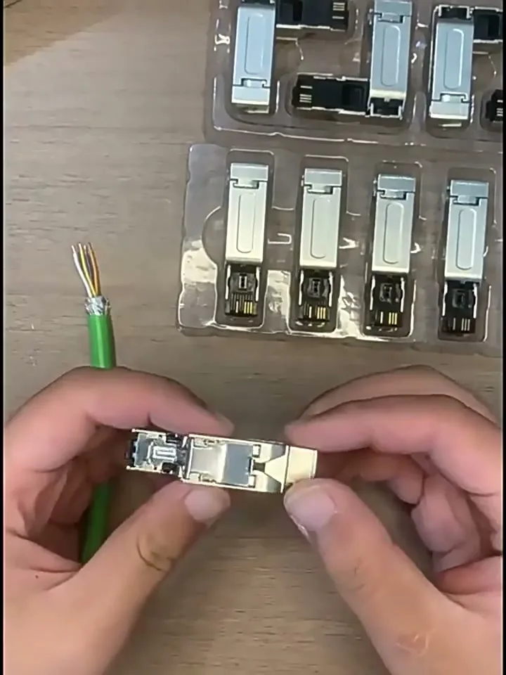 The RJ45 field-wireable connector as supplied, before opening.
The connector as supplied. Inside the shell it consists of three parts:
- Contact block — the black carrier with spring-loaded IDC contacts and a hinged cover
- Top shell half — nickel-plated copper-zinc alloy
- Bottom shell half — carries the RJ45 blade nose and the cable-entry collar
Step 1 — Open the connector
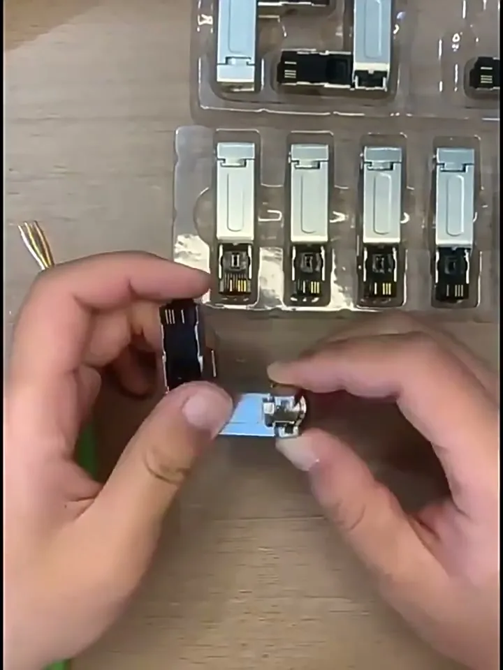 Separating the connector to reach the contact block.
Hold the assembled connector and lift the two shell halves apart. They hinge at the nose end and snap apart at the cable end with light finger pressure. Leave the two halves joined at the nose — you only need to open the cable end like a book.
Step 2 — Prepare the cable
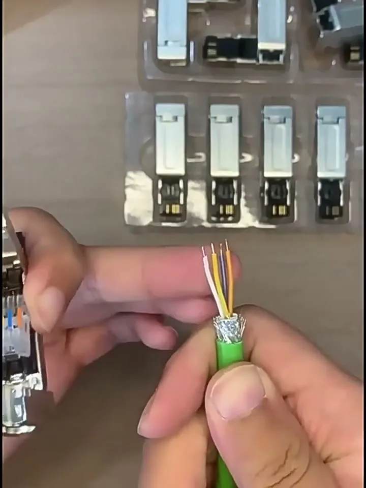 The prepared cable end: jacket removed, braid shield folded back, four insulated conductors fanned out.
- Strip the outer jacket back about 25 mm — enough for the conductors to reach their channels with the jacket seated in the collar.
- Fold the foil and braid shield back over the jacket, out of the way. Do not cut it off; it must end up clamped between the shell halves.
- Untwist the pairs only as far as needed — keep any untwisted length under about 13 mm to protect the cable's electrical performance.
- Do not strip the individual conductors. The IDC contacts cut through the insulation themselves. Trim the conductor ends evenly with flush cutters.
ℹ Verify before use: confirm the jacket strip length and the approved cable OD range against the current datasheet — values vary by cable type.
Step 3 — Open the IDC cover
Flip the contact block's hinged cover fully open. You will see the wire channels and, on most versions, the channel numbers moulded next to them.
Step 4 — Lay the conductors
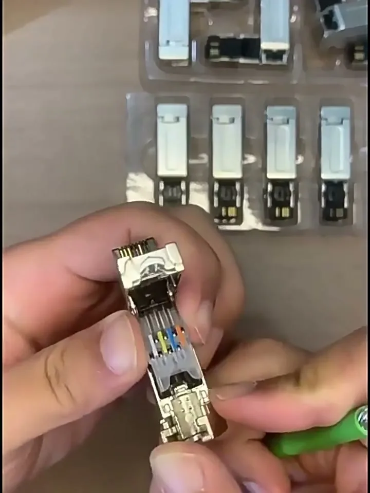 The four conductors laid into the contact block channels, colours visible.
Lay each conductor into its channel and push it fully home with a fingertip. For the 4-contact models the pairs land on contacts 1–2 and 3–6 of the RJ45 footprint:
| Contact | PROFINET cable colour | T568B cable colour | Signal |
|---|---|---|---|
| 1 | Yellow | White–Orange | TD+ |
| 2 | Orange | Orange | TD− |
| 3 | White | White–Green | RD+ |
| 6 | Blue | Green | RD− |
The cable in this guide is a PROFINET cable (white / orange / blue / yellow). Other industrial 2-pair cables may use manufacturer-specific colours. What matters is the pair mapping, not the colour names: one pair goes to contacts 1–2, the other to contacts 3–6, with the polarity consistent at both ends of the link. Follow the channel markings on the contact block and your cable datasheet.
Wiring the 8-contact M08 versions? All four pairs are needed for Gigabit Ethernet. Use the full T568B order: 1 white-orange, 2 orange, 3 white-green, 4 blue, 5 white-blue, 6 green, 7 white-brown, 8 brown. Or T568A throughout, if that is your plant standard — just be consistent at both ends.
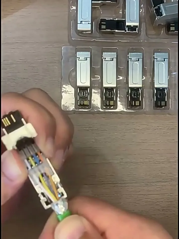 All four conductors fully seated in the channels before the cover is closed.
Check that every conductor bottoms out in its channel and that none has jumped across to a neighbouring channel.
Step 5 — Close the cover
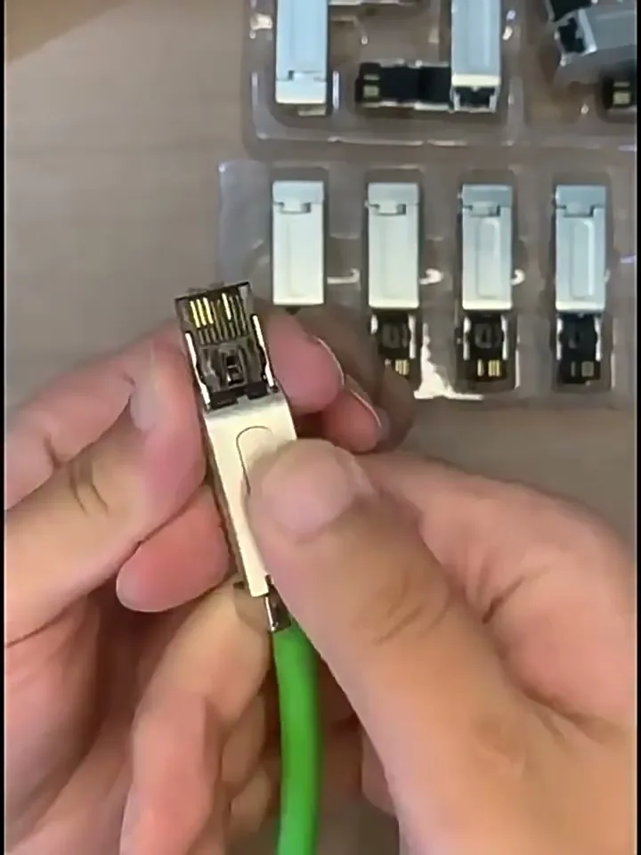 Pressing the hinged cover down until it latches over the conductors.
Press the cover down firmly with your thumb until both sides latch. The IDC contacts pierce the insulation and grip each conductor — no stripping, no screws, no re-torquing later.
Step 6 — Close the metal shell
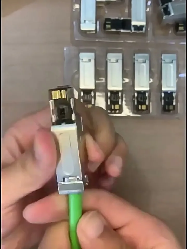 The nickel-plated shell closed around the contact block, with the cable clamped.
Fold the two shell halves back around the contact block, tucking the folded shield under the shell clamp as they close. Squeeze until the tabs snap — you should feel and hear the latch. The shell provides 360° shield contact end to end and clamps the jacket for strain relief.
Result
Give the connector a gentle tug on the cable and a visual check: jacket clamped, shield hidden under the shell, no conductor visible in the channels.
Straight or right-angle?
Both models terminate identically — the only difference is the exit direction. Use the straight body where the cable runs perpendicular to the port; use the right-angle body where a side exit avoids a sharp cable bend next to the machine wall.
Verification checklist
| Check | How |
|---|---|
| Pair polarity | Cable tester, or swap test with a known-good patch cable |
| Continuity 1-2-3-6 (all 8 contacts for M08), no shorts | Cable tester with wire-map display |
| No split pair | Wire-map test — a split pair passes a simple continuity test but kills the link |
| Shield continuity | Measure between the two connector shells at each end of the run |
| Strain relief | Firm tug on the cable — nothing moves |
| Latch | Both shell tabs and the cover latched, no gap |
Common mistakes
| Mistake | Result |
|---|---|
| Untwisting the pairs back too far | Return loss fails; flaky link at long runs |
| Cutting the shield off instead of clamping it | No EMC protection; intermittent faults near VFDs |
| Stripping the conductor insulation | IDC contacts cannot grip bare strands reliably |
| Conductor in the wrong channel (swapped 3 and 6) | No link, or a link that drops under traffic |
| Cover not fully latched | High-resistance contact that fails weeks later |
| Jacket left outside the collar | All cable force lands on the contacts |